
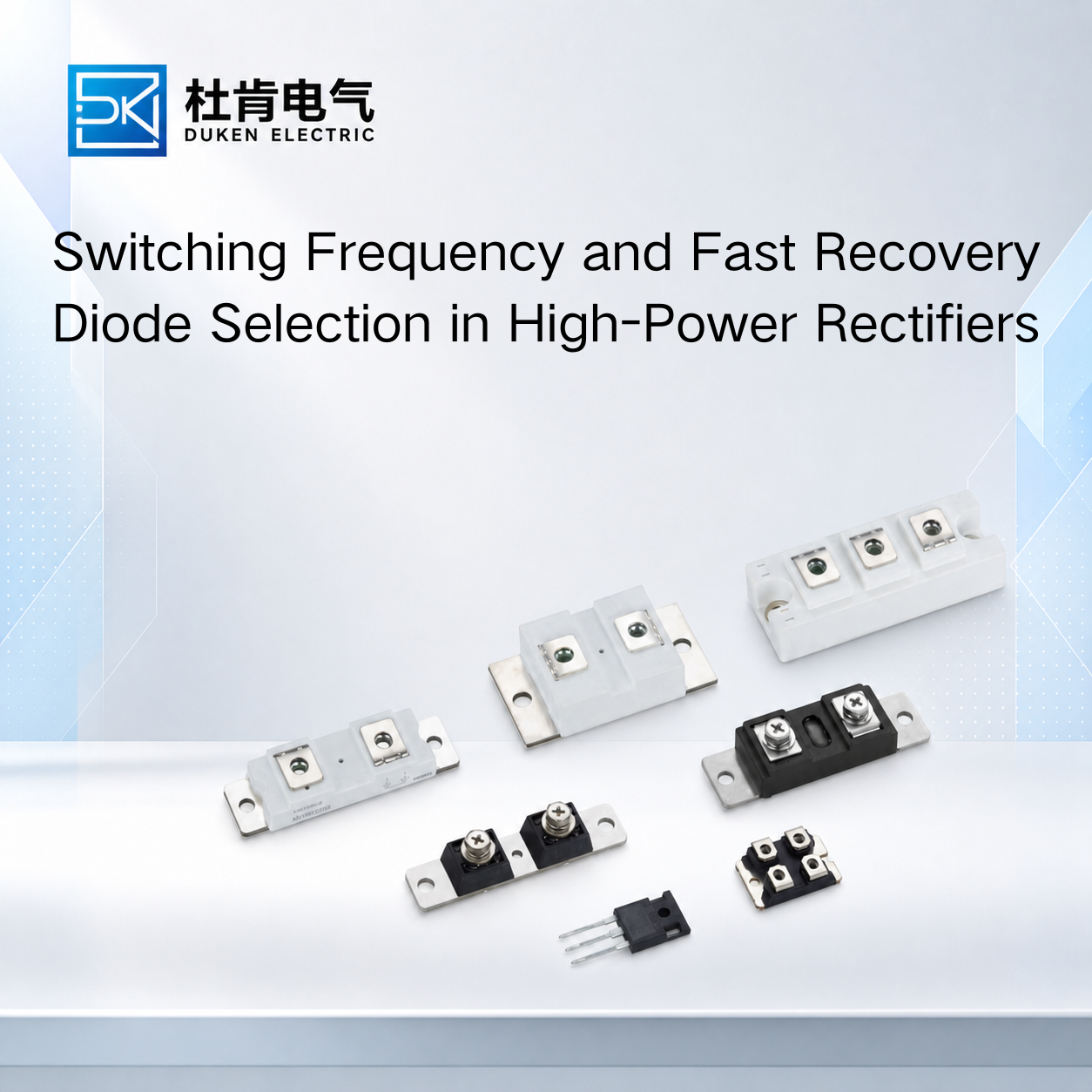
Switching Frequency and Fast Recovery Diode Selection in High-Power Rectifiers
Author: Selina
The Impact of Switching Frequency on Fast Recovery Diode Selection is a critical consideration for engineers designing industrial rectifiers, welding power supplies, and high-frequency power converters. A diode that performs efficiently at 10 kHz may produce significantly greater switching losses at 50 kHz, even when its current and voltage ratings remain unchanged. For OEM manufacturers and industrial component buyers, selecting the appropriate fast recovery diode requires understanding reverse recovery behavior, forward conduction losses, thermal performance, and the switching characteristics of the surrounding circuit.
1. Why Switching Frequency Changes Diode Performance
Fast recovery diodes are designed to transition from forward conduction to reverse blocking more quickly than conventional rectifier diodes.
This process produces reverse recovery current.
Reverse Recovery Time and Charge
Two important parameters describe diode switching behavior:
Reverse recovery time (trr): The time associated with the transition from forward conduction to reverse blocking under specified test conditions.
Reverse recovery charge (Qrr): The charge removed during reverse recovery, typically determined by integrating the reverse recovery current waveform.
Although trr is frequently highlighted in product catalogs, Qrr and the recovery-current waveform are also important because they influence switching losses and stress on adjacent semiconductor switches.
For a simplified first-order estimate, recovery-related switching energy may be approximated as:
Where:
(V_R) is the relevant reverse voltage.
(Q_{rr}) is the reverse recovery charge.
The associated average power is approximately:
Here, (f_s) represents the switching frequency.
These expressions are useful for preliminary comparison, but actual losses depend on voltage and current waveforms, commutation behavior, circuit parasitics, and the manufacturer's test conditions.
Frequency and Power Loss
Consider two otherwise comparable operating cases.
If a diode dissipates 0.4 mJ of recovery-related energy per switching event, its estimated recovery-related power is:
Switching Frequency | Estimated Recovery-Related Power |
|---|---|
10 kHz | 4 W |
20 kHz | 8 W |
50 kHz | 20 W |
100 kHz | 40 W |
These figures are illustrative calculations, not specifications for a particular 200A diode.
They demonstrate why switching frequency must be considered during thermal design.
The Impact of Switching Frequency on Fast Recovery Diode Selection becomes particularly important when switching losses approach or exceed the available thermal margin.
2. Balancing Fast Recovery and Low Conduction Loss
Selecting the diode with the shortest advertised recovery time does not necessarily produce the most efficient converter.
The device must also provide acceptable forward conduction characteristics.
Forward Voltage and Conduction Loss
A diode's forward voltage drop influences power dissipation during conduction.
For a simplified constant-voltage approximation:
Where (V_F) is the assumed forward voltage and (I_{avg}) is the average forward current over the complete operating period.
More accurate analysis uses the actual forward voltage-current characteristic and current waveform.
For example, a diode with a 1.2 V forward drop carrying a constant 100 A would dissipate approximately 120 W during conduction.
This example is illustrative and should not be interpreted as a datasheet rating.
High-Power Rectifier Requirements
A purchasing specification such as fast reverse recovery for high power rectifier low conduction loss 200A 400V fast recovery diode combines several important requirements.
The 200A rating must be interpreted according to the datasheet's specified current definition, case temperature, conduction waveform, and cooling conditions.
Similarly, a 400V reverse-voltage rating must be evaluated against the maximum repetitive reverse voltage, transient overshoot, and required design margin.
Engineers should review:
Parameter | Selection Purpose |
|---|---|
VRRM | Maximum repetitive reverse blocking capability |
IF(AV) | Average forward current rating |
IF(RMS) | RMS forward current for thermal evaluation |
IFSM | Non-repetitive forward surge capability |
VF | Forward voltage under specified conditions |
trr | Reverse recovery timing |
Qrr | Recovery charge |
IR | Reverse leakage current |
RthJC | Junction-to-case thermal resistance |
Tj(max) | Maximum rated junction temperature |
A fast reverse recovery for high power rectifier low conduction loss 200A 400V fast recovery diode should therefore be evaluated using both conduction and switching losses rather than one headline parameter.
Comparing Fast Recovery and Standard Rectifier Diodes
Conventional rectifier diodes are often suitable for line-frequency AC rectification.
However, their reverse recovery characteristics may be unsuitable for high-frequency switching circuits.
Fast recovery diodes are generally better suited to applications where repeated rapid commutation occurs.
The appropriate choice depends on circuit frequency, voltage, current, and efficiency requirements.
3. Switching Frequency Considerations in Welding Equipment
Industrial welding machines present demanding conditions for power semiconductors.
Modern inverter welding systems often use high-frequency switching to reduce transformer size and improve output control.
The output rectifier must handle substantial current while maintaining acceptable switching and conduction losses.
Stud-Type Diode Construction
A requirement such as 3/4″-16UNF stud type low reverse leakage current used in welding machine 200A 400V fast recovery diode identifies a specific mechanical mounting configuration.
Stud-mounted diodes provide a mechanical connection that can also form part of the electrical and thermal path, depending on device construction.
However, thread size alone does not establish interchangeability.
Engineers must confirm:
Thread specification and mounting dimensions
Stud polarity
Terminal configuration
Recommended mounting torque
Heat-sink interface requirements
Electrical and thermal ratings
The exact tightening torque must come from the manufacturer's documentation. Applying an assumed torque may damage the device or compromise thermal contact.
Reverse Leakage and Thermal Stability
Reverse leakage current typically increases with junction temperature.
Although leakage losses may be relatively small compared with conduction losses in many applications, excessive leakage can contribute to thermal stress, particularly at elevated temperatures.
For a 3/4″-16UNF stud type low reverse leakage current used in welding machine 200A 400V fast recovery diode, leakage specifications should be compared at equivalent reverse voltages and temperatures.
A room-temperature leakage value alone is insufficient for evaluating performance in a hot welding-machine enclosure.
Welding Duty Cycle
Welding systems often experience intermittent high-current operation.
The diode must tolerate the specified load profile, including conduction intervals, temperature cycling, and occasional current surges.
Buyers should request thermal impedance information when the application involves pulsed loading.
This helps engineers evaluate junction-temperature changes during actual welding cycles.
4. Soft Recovery and Reliability in Power Modules
Reverse recovery behavior is not defined by recovery time alone.
The shape of the recovery-current waveform can strongly influence circuit performance.
Hard Recovery Versus Soft Recovery
A diode with abrupt reverse recovery may produce a rapid change in current.
Combined with circuit inductance, this can generate voltage overshoot and ringing.
A soft recovery diode exhibits a more gradual reduction in reverse recovery current under its specified operating conditions.
This characteristic can help reduce switching transients and electromagnetic interference.
For a high reliability power module soft recovery type 200A 400V fast recovery diode, engineers should examine the recovery waveform, softness characteristics where specified, and relevant test conditions.
Soft recovery does not automatically mean lower total recovery charge or lower total switching energy.
Both characteristics must be evaluated independently.
Integration With IGBT-Based Converters
Fast recovery diodes are commonly associated with IGBT power-conversion circuits.
During switching transitions, diode reverse recovery can increase the current stress experienced by the commutating IGBT.
This affects switching energy, temperature rise, and electromagnetic compatibility.
A high reliability power module soft recovery type 200A 400V fast recovery diode may be appropriate where controlled recovery behavior is more valuable than simply minimizing the published trr value.
However, the diode must still satisfy the converter's voltage, current, thermal, and mechanical requirements.
Comparison With Other Semiconductor Technologies
Device | Switching Characteristics | Typical Use |
|---|---|---|
Standard Rectifier Diode | Generally optimized for lower-frequency rectification | AC line rectifiers |
Fast Recovery Diode | Reduced reverse recovery time | Switching converters |
Soft Recovery Diode | Controlled recovery-current decay | High-power converters |
SiC Schottky Diode | Negligible minority-carrier reverse recovery | High-frequency power conversion |
IGBT | Actively controlled power switch | Industrial inverters |
MOSFET | Fast gate-controlled switch | DC-DC converters |
SiC Schottky diodes can substantially reduce reverse recovery-related losses, although capacitive switching effects remain.
Their suitability depends on voltage class, current capability, thermal behavior, package availability, and cost.
A direct substitution should not be approved without application-level evaluation.
5. Practical Selection and Procurement Recommendations
The Impact of Switching Frequency on Fast Recovery Diode Selection should be evaluated through the complete operating profile rather than a single nominal frequency.
Define the Actual Electrical Conditions
Before requesting quotations, OEM engineers should document:
Switching frequency range
Maximum repetitive reverse voltage
Average and RMS forward current
Peak and surge current requirements
Expected junction-temperature range
Cooling configuration
Mechanical package requirements
Switching topology and commutation conditions
Compare Datasheets Under Equivalent Conditions
Recovery time and recovery charge depend on forward current, reverse voltage, current fall rate, and junction temperature.
Two datasheets using different test conditions cannot be compared reliably by looking only at the published trr values.
Where possible, request characteristic curves or application-test information.
Validate the Complete Thermal Design
Total diode dissipation includes conduction losses, reverse recovery-related losses, and reverse leakage losses.
The cooling system must keep junction temperature within the manufacturer's specified limits under the intended duty cycle.
For replacement projects, mechanical compatibility and thermal interface requirements should be verified before installation.
FAQ
1. Does increasing switching frequency always increase diode losses?
For a fixed energy loss per switching event, increasing switching frequency increases average switching power. However, actual loss also depends on operating waveforms and conditions.
2. Is the diode with the shortest trr always the best choice?
No. Forward voltage, recovery charge, recovery softness, thermal resistance, and circuit compatibility are also important.
3. Can a 200A 400V fast recovery diode be used in a welding inverter?
Potentially, if its voltage, current, recovery, thermal, surge, and mechanical characteristics satisfy the actual circuit requirements.
4. What is the advantage of soft recovery in industrial power modules?
Soft recovery can reduce abrupt current changes, helping control voltage overshoot, ringing, and electromagnetic interference.
5. Can a SiC diode replace a silicon fast recovery diode?
In some designs, yes. However, the replacement requires verification of electrical ratings, capacitive behavior, thermal performance, package compatibility, and overall circuit operation.
Conclusion
The Impact of Switching Frequency on Fast Recovery Diode Selection extends beyond choosing a device with a low reverse recovery time. As switching frequency increases, recovery-related losses, thermal stress, and switching transients become increasingly important.
For high-power rectifiers, engineers must balance low conduction losses with suitable reverse recovery characteristics. Welding equipment introduces additional requirements involving stud-package compatibility, leakage behavior, and intermittent high-current operation. Industrial power modules may benefit from soft recovery characteristics that help control switching transients.
By comparing datasheet parameters under consistent test conditions and validating the diode within its intended circuit, OEM manufacturers and procurement teams can select devices that support efficiency, reliability, and long-term equipment performance.
READ MORE: